123Next
Return to list New
View: 5300|Reply: 23

GTR6 where to adjust voltage?

[Copy link]

4

Threads

17

Posts

100

Credits

Member

Rank: 2

Credits
100
Post time 2023-02-08 10:23:10 | Show all posts |Read mode
Hi,

My GTR6 work well with 3375 Mzh & -130mV offset (use AATU Software)

with these settings, the PC can:
CinebenchR23 score around 13800-13900 points
Stable at >4.0Ghz & 90 degree (it's okay as I dont have many heavy daily tasks)

Now I want to change the fix number in BIOS (something like offset mode voltage). But cannot find anywhere to change this setting except the P-State.
Anyone know how to change these setting?

If the P-state is only choice:
I tried to change P-state 2-3 times, but the PC is soft bricked after that and I have to reflash the BIOS chip (clear CMOS cannot work with invalid P-state setting).
Very time consuming to play with P-state. But if it's the only choice, do you have any experience or recommend for me?

The P-State note in BIOS that:
"Disable - disable this P-state custom
Customeize this P-state, applicable only if PcdOcDisbale = FALSE"
I cannot find any where the PcdOcDisable setting in the Bios.

Btw, should I try to disable PSS Support in CPU Configuration?

P/S: Beelink support is totally useless during this month. I email alot, and they are silent.


Reply

Use magic Report

4

Threads

17

Posts

100

Credits

Member

Rank: 2

Credits
100
 Author| Post time 2023-02-10 11:36:41 | Show all posts
Edited by zungnguyen at 2023-02-10 11:55
Magister replied at 2023-02-10 02:50
When you brick it playing with pstate0, how do you reflash the BIOS chip?

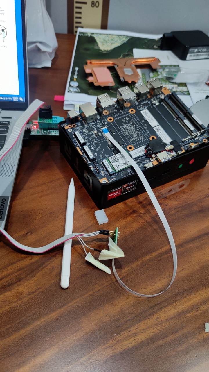
A little bit intermediate task:

+ You need an USB CH341 Programmer support 1.8 voltage BIOS chip (you can order on aliexpress, which is very cheap). They will provide  a connect cable CLIP with the USB (this is important)
+ a small PCB to transform FFC to 2.54mm holes for customize.
+ NEOPROGRAMMER software (latest version)
+ a FFC cable 0.5cm 10 pin.
+ a digital multimeter

Now, under the SSD position, you will find a FFC jack to connect the cable. all the pin face down.
Remove the clip to get 8 copper leg of the connect cable (provided with the USB CH341)
Solder the 8 copper leg to the small PCB in right order:
Pin 6 of cable to hole 1 of PCB
Pin7 of cable to hole 2 of PCB
Pin 5 of cable to hole 4 of PCB
Pin 8 of cable to hole 5 of PCB
Pin 9 of cable to hole 6 of PCB
Pin 10 of cable to hole 8 of PCB

Next, connect everything, unplug the PC (both monitor & adapter).
Open Neoprogrammer, detect the CHIP. if it return W25Q256JW chip type, everything is okay)

Download BIOS of beelink Gtr6, open the .rom file and write to the chip.
The PC will work!

I brick my PC everyday!!!!
connecting.jpg
Reply Support 2 Not support 0

Use magic Report

5

Threads

2311

Posts

7144

Credits

Super Moderator

Rank: 8Rank: 8

Credits
7144
Post time 2023-02-08 17:23:23 | Show all posts
Hello,
Could you send a picture of your bios version and SN code?
Reply Support 1 Not support 0

Use magic Report

4

Threads

17

Posts

100

Credits

Member

Rank: 2

Credits
100
 Author| Post time 2023-02-08 22:46:06 | Show all posts
Edited by zungnguyen at 2023-02-09 09:26

SN.jpg


Reply Support Not support

Use magic Report

4

Threads

17

Posts

100

Credits

Member

Rank: 2

Credits
100
 Author| Post time 2023-02-09 10:01:30 | Show all posts
Edited by zungnguyen at 2023-02-09 23:22
Support-03 replied at 2023-02-08 17:23
Hello,
Could you send a picture of your bios version and SN code?

Hi mate,
SN: 6900H2CG40074 GTR6-A-32512VK0W64PRO-A2
BIOS is from: Bios: MiniPCFP7HDF722007_GTR6_P5C4V16_20221108103000_SsidSvid.rom
bios.jpg
Reply Support Not support

Use magic Report

4

Threads

114

Posts

878

Credits

Senior Member

Rank: 4

Credits
878
Post time 2023-02-10 02:50:31 | Show all posts
When you brick it playing with pstate0, how do you reflash the BIOS chip?
SER5 5600H 32/500 - MX Linux
Reply Support Not support

Use magic Report

5

Threads

2311

Posts

7144

Credits

Super Moderator

Rank: 8Rank: 8

Credits
7144
Post time 2023-02-10 17:49:30 | Show all posts
Hello,
Pls send a picture of the main page in the bios,
Reply Support Not support

Use magic Report

4

Threads

17

Posts

100

Credits

Member

Rank: 2

Credits
100
 Author| Post time 2023-02-11 02:42:22 | Show all posts
Support-03 replied at 2023-02-10 17:49
Hello,
Pls send a picture of the main page in the bios,

Hi,
Here is the BIOS main page:
bios main page.jpg
Reply Support Not support

Use magic Report

0

Threads

41

Posts

363

Credits

Full Member

Rank: 3Rank: 3

Credits
363
Post time 2023-02-12 18:36:54 | Show all posts
zungnguyen replied at 2023-02-11 02:42
Hi,
Here is the BIOS main page:

Why don't you use the standard clip for the W25Q256JW chip, which is included with the USB programmer? Which kit is better suited for reprogramming BIOS GTR6 - CH341A or CH341B?
Reply Support Not support

Use magic Report

4

Threads

17

Posts

100

Credits

Member

Rank: 2

Credits
100
 Author| Post time 2023-02-12 20:05:59 | Show all posts
Anatol replied at 2023-02-12 18:36
Why don't you use the standard clip for the W25Q256JW chip, which is included with the USB program ...

w25Q256jw cannot be clipped. You have to desolder the Chip or to use the FFC jack under the SSD.
I use Neoprogrammer, so it work well with CH241A (but need volt mod or a 1.8v adapter)
Reply Support Not support

Use magic Report

You have to log in before you can reply Login | Sign up

Points Rules

Quick Reply To Top Return to the list